Logic Probe Plans
This is a set of plans for an inexpensive, high performance digital logic probe that you can build in a few hours. It is small enough to use a plastic ball-point pen as a chassis, giving it a personalized touch and added style. The main advantage of this design is that the LED will only light when the probe tip is touching a voltage source (not floating). This is a necessary feature when working with tri-state logic, and is overlooked by most logic probe plans found in textbooks.
Schematic Diagram

| Resistor: | Value (ohms): |
|---|---|
| R1, R4, R5, R6 | 1 MΩ |
| R2, R3 | 100 KΩ |
| R7 | 330 Ω |
Parts List
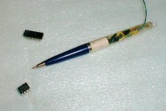
- Ball-point pen - This will be the housing for the logic probe. Chose a pen that unscrews at the middle, has a large barrel, and is made of plastic. (Metal will cause short-circuits, unless you are really careful.)
- Bicolor LED - Use a standard red/green bicolor LED or two individual LED's wired in reverse parallel.
- Dual op-amp - Chose an op-amp that is sensitive, has good rail-to-rail characteristics, a large input impedance, and an output current greater than 20 mA. Radio Shack part number 276-1715 should work well.
- Resistors - See the schematic for values.
- Probe tip - You can use a short piece of brass rod, a needle, the tip of a paper clip, or whatever.
- Two alligator clips - One should be red and the other should be black.
- Wire wrap wire
- Epoxy
Assembly Instructions
Prepare the pen by removing the ink cartridge and by cleaning out any ink residue. Solder the probe tip to R2 and R3 as shown in the schematic and epoxy this assembly into the bottom of the pen. While the epoxy dries, prepare the top half of the pen for the LED by drilling a mounting hole if necessary. Drill another smaller hole in the side of the pen for the power leads to enter.
Assemble the rest of the circuit as shown in the schematic above with wire wrap wire. Try to keep it as small as possible. Leave about 3 feet of loose wire for alligator clips one and two, but do not yet connect the alligator clips themselves. When the epoxy is dry, attach R2 and R3 to the rest of the circuit.
Test the circuit by attaching the wire for alligator clip one to the positive terminal of a five volt power supply and the wire for alligator clip two to the negative terminal of the power supply. The LED should not light. Now touch the tip of the probe to the positive terminal of the power supply. The LED should light red. Now touch the tip of the probe to the negative terminal of the power supply. The LED should light green. If the LED lights red on the negative terminal and green on the positive one, reverse its polarity by rewiring it. If the LED does not light at all, check your wiring. If all else fails, the op-amp may not be designed to operate at five volts. Consider replacing it with a different model.
When you finish testing the circuit, mount it in the ball-point pen. Feed the three feet of loose wire for alligator clips one and two through the smaller hole near the top of the pen, keeping track of which wire is which. Solder the red alligator clip to the wire for alligator clip one, and then solder the black alligator clip to the wire for alligator clip two. Insert the LED into its mounting hole, and secure it with epoxy. Finally, screw the pen together and test it one more time. If the probe does not work, unscrew the pen and try again. If works, you're done!
How to Use the Logic Probe
Your new logic probe is very easy to use. To test the voltage of a logic circuit at any given point, first connect the power (alligator) clips to the circuit's power supply. Next, touch the tip of the probe to the point you want to test. The LED will light green for a voltage less than 9/20 the power supply voltage and red for a voltage greater than 11/20 the power supply voltage. A high-frequency signal will cause the LED to oscillate between red and green, appearing orange.